I've been working for a while on a program that automatically generates analog electronic circuits using evolutionary algorithms. It's still very much a work in progress, but I've used it to generate some useful circuits. Current workings of the program is as follows:
- Programmer decides a goal function, possible constraints, simulation type(AC, DC, Transient), number of nodes and types and values of the components available. Possibly tweaks genetic algorithm parameters, such as: population size, mutation probability etc...
- First generation of circuits is randomly generated and they are simulated in SPICE(I use ngspice).
- Outputs of the simulations are ranked against the goal function and good performers are mutated and added to the new generation of circuits.
- This is repeated until a good enough circuit is found.
For example I have used it to find inverter circuits, bandgap references and rising edge detectors.
BJT Inverter, with 4 components
First circuit that I evolved was a inverter using bjt transistors. Options were:
- Maximum of 4 components.
- Allowed components: 2N3904 and 2N3906 transistors and resistors with values of 0.1 to 10M Ohms.
- I also provided one 5V power supply.
- SPICE simulation was DC sweep from 0 to 5V and the goal was transition on 2.5V. Rise and fall times were not tested.
Below is an animated gif of the responses of the best circuits:
As you can see the response improved quickly and last big breakthrough was in generation 78 and it took only 9 minutes to get there. Generation 2049 was reached 6.5 hours after starting.Currently the program isn't multithreaded and circuits are tested one at a time. Simulating more circuits at the same time should improve the simulation time linearly depending on number of available processor cores.
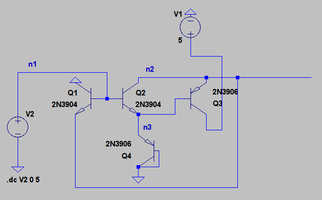
The best circuit in generation 70
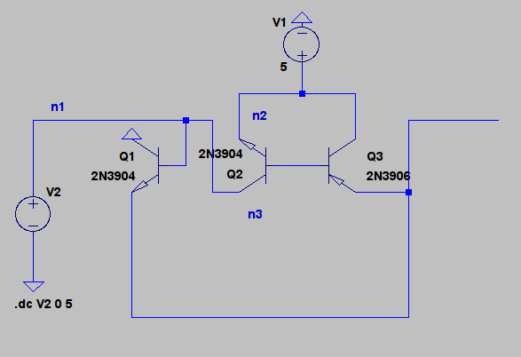
The best circuit in generation 78
If you compare the circuits in the generations 70 and 78 you can see that the breakthrough was in reconnecting Q2, it's base was connected to the base of Q3 and collector was connected to the input. Q4 was also removed but it didn't really do anything because it was permanently in the cutoff state. There's no more big changes and rest of the time was spent on trying to find a suitable fourth component. In the final circuit, generation 2049, fourth component was resistor and circuit greatly resembles a CMOS inverter.
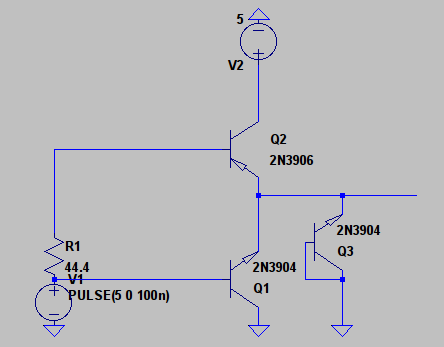
Circuit in generation 2049(If you are wondering what Q3 does, it doesn't really do anything.)
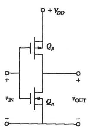
CMOS inverter
This is looks like it might work, but if we plot currents taken from input and current going to ground. We see that maximum current taken from the power supply is 200mA. This is horribly inefficient and it's probably more than the transistors can handle.

Currents at the collectors of the transistors
And if we look at the base current of Q1 maximum current is 210mA when input is at 5V. This is too much for 2N3904 transistor and real transistor would probably break.

Base current of Q1 as a function of input voltage
It makes sense that if power consumption of the circuit isn't tested it will evolve so that it doesn't care about power consumption. It's easier to use lots of power than to use a little of it.
One problem is also that SPICE is happy to simulate that current through transistor is 100A, even if it clear that real component wouldn't be able to withstand that much current. To make this program useful it's probably necessary to add checks that power used by components is reasonable.
Bandgap reference
Another circuit that I evolved is a bandgap reference. Goal was to generate stable 2.5V output voltage when the supply voltage varied from 4V to 10V. SPICE can also simulate temperature so added two input DC sweep with temperatures of 27 and 60 degrees Celsius. This time number of components was restricted to eight and components available were same as in the inverter evolution(2N3904 and 2N3906 transistors and resistors).
Below are animated gifs of output voltages on different temperatures as a function of input voltage, I also added the current score to the plot:
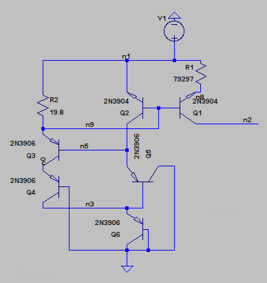
The final bandgap circuit

Output voltage as a function of input voltage, temperature: 27 degrees
Because converting SPICE netlist to schematic must be done by hand and is time consuming I'm only giving a schematic of the final circuit.
As you can see on the output sweep that the reference isn't that accurate and this circuit also has a power consumption problem. R2 is only 20 Ohms and it takes lots of current from the power supply, when supply voltage is high. If R2 is changed to a bigger value output voltage drops slightly. I exchanged it to a 10k resistor and output voltage drops to 1.3V and current taken from the supply is only 0.5mA when input voltage is 4V and 1.4mA when voltage is 10V. This starts to be a reasonable current considering that transistors used are discrete components. If this was an integrated circuit it would be still a too big current.
Other problem that this circuit has is that it's output voltage drops when the output is loaded.

Output voltage as a function of input voltage with different load resistances
In the above picture output voltage is swept and load resistance is stepped from 1k to 100k with a step of 10k. With 100k load 1.3V reference becomes 1.25V reference and output voltage decreases quickly when load resistance is decreased with a 1k load reference doesn't work correctly anymore. This plot is made with R2 changed to 10k.
With 100k load output voltage is 1.39V when input voltage is 10V and 1.29V when input voltage is 4V. Output voltage rises about 1.6mV per 1V increase in input voltage.
If temperature is 60 degrees Celsius. Output voltage is 1.18V when input is 4V and 1.29V when input is 10V. Temperature dependency is about -3mV per degree Celsius. Not very good as a reference but considering that this was generated automatically I think it's a success, even tough it's output voltage isn't 2.5V as was required. Allowing more components would have probably generated a more accurate reference.
I would make this circuit using real components and test how it performs in real life, but I don't have enough transistors.
If you are interested in the code it's available at my github account, but I must warn you that it's not easy to use and requires a Linux OS and ngspice for simulating circuits, but I would still appreciate any contributions.
I think this looks promising and if I can implement automatic check for used power and that currents and voltages are reasonable for real components, it might be actually useful.